Markeren:
Dichte Fase het Pneumatische Vervoeren Pomp
, hoge efficiëntie silo pomp
, materiaaloverdrachtsbakpomp
Naam: |
pneumatische silo pomp |
Model: |
PCD |
Tankstructuur: |
Verticale cilinder |
Binnendiameter pomp: |
800 mm, 1200 mm, 1400 mm, 2400 mm |
Prestatie: |
Dichtfase positieve druk transport |
Toepassingen: |
Vliegas van energiecentrales, cement, grondstoffen, mineraalpoeder, etc. |
Hoofdmateriaal: |
Q235 koolstofstaal, 304 roestvrij staal, 316 roestvrij staal |
Applicatie: |
Vliegas van energiecentrales, metallurgie, mijnbouw, chemische industrie, enz. |
Doel: |
Vervoer van poedermaterialen |
Klepconfiguratie: |
De toevoerklep maakt gebruik van een conische klep en de afvoerklep maakt gebruik van een slijtvaste |
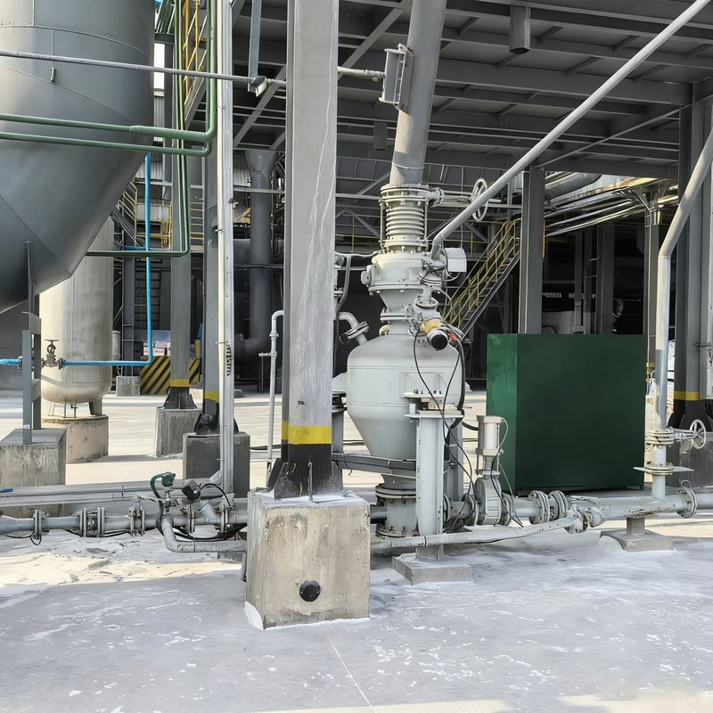
Dichte fase pneumatische transportbakpomp. Silo-pomp.
Structurele samenstelling
Hoofdvat: typisch geconfigureerd als een verticale cilinder, met enkele horizontale ontwerpen.voor gebruik in Q235 koolstofstaal of 304/316 roestvrij staalGrote vaten zijn vaak verdeeld in bovenste en onderste kamers, gescheiden door een stroomleidingskegel of een verdelingsplaat.met een diameter van niet meer dan 20 mm,.

Parametertabel van de pneumatische pomp voor grote capaciteit
| Vervoermateriaal |
Bulkdichtheid (t/)m3) |
Model |
PCD24/H |
PCD26/H |
PCD28/H |
PCD30/H |
Vervoersafstand |
| Specificatie |
16 tot en met 20 m3 |
18 tot en met 22 m3 |
20 tot en met 27 m3 |
26 tot en met 32 m3 |
Niveau (m) |
Niveau (m) |
| Gepulverde steenkool |
0.5 |
Leveringsvolume (t/h) |
50 tot 80 |
60 tot 90 |
65 tot 110 |
80~130 |
200 |
20 |
| Vliegas |
0.75 |
75 tot 125 |
85 tot 130 |
95 tot 160 |
125 tot 190 |
200 |
20 |
| Kalksteenpoeder/mineraalpoeder |
0.8 |
80~130 |
90 tot 140 |
100~170 |
130~200 |
200 |
20 |
| Cement/ruwe meel |
1 |
100 tot 150 |
115 tot en met 175 |
130 tot 215 |
165 tot 260 |
200 |
20 |
Parametertabel van de pneumatische transportbak voor pompen voor lange afstanden
| Vervoermateriaal |
Bulkdichtheid (t/m3) |
Model |
PCD24/L |
PCD26/L |
PCD28/L |
PCD30/L |
Vervoersafstand |
| Specificatie |
16 tot en met 20 m3 |
18 tot en met 22 m3 |
20 tot en met 27 m3 |
26 tot en met 32 m3 |
Niveau (m) |
Niveau (m) |
| Gepulverde steenkool |
0.5 |
Leveringsvolume (t/h) |
20 tot 40 |
25 tot 45 |
30 tot 55 |
45 tot 65 |
1000 |
25 |
| Vliegas |
0.75 |
35 tot 60 |
45 tot 65 |
45 tot 80 |
65 tot 95 |
1000 |
25 |
| Kalksteenpoeder/mineraalpoeder |
0.8 |
40 tot 65 |
45 tot 70 |
50 tot 85 |
70 tot 100 |
1000 |
25 |
| Cement/ruwe meel |
1 |
50 tot 80 |
55 tot 90 |
65 tot 110 |
90 tot 120 |
1000 |
25
|
Parametertabel van de pneumatische vervoersbak met conventionele roosterpompen
| Vervoermateriaal |
Bulk Density ((t/m3) |
Model |
PCD18/N |
PCD20/N |
PCD20/N |
Referentietransportafstand |
| Specificatie |
5.0~6.7m3 |
7.0 tot 10.0m3 |
10.0 tot en met 15.0 m3 |
Niveau (m) |
Verticaal (m) |
| Gepulverde steenkool |
0.5 |
Leveringsvolume (t/h) |
12 tot 20 |
16 tot 32 |
25 tot 50 |
500 |
30 |
| Vliegas |
0.75 |
18 tot 32 |
25 tot 48 |
35 tot 70 |
50 |
|
| Kalksteenpoeder/mineraalpoeder |
0.8 |
20 tot 35 |
26 tot 51 |
38 tot 75 |
500 |
30 |
| Cement/ruwe meel |
1.0 |
24 tot 42 |
32 tot 65 |
48 tot 95 |
500 |
30 |
| Siliciumpoeder |
1.2 |
28 tot 50 |
40 tot 75 |
55 tot 115 |
500 |
30
|
Parametertabel van kleine pneumatische bunkerpomp
| Materiaal |
Bulk Density ((t/m3) |
Model |
PCD08/M |
PCD10/M |
PCD12/M |
PCD14/M |
Referentietransportafstand |
| Specificatie |
0.2~0.5m3 |
0.6 ~ 1.6m3 |
1.5 tot 2.5m3 |
2.5 tot 5.0m3 |
Niveau (m) |
Verticaal (m) |
| Gepulverde steenkool |
0.5 |
Leveringsvolume (t/h) |
0.5 tot 1.8 |
1.5 tot 5.5 |
5.0~9.0 |
8.0~18.0 |
100 |
20 |
| Vliegas |
0.75 |
0.9~2.8 |
2.5 tot 8.5 |
7.0 tot 14.0 |
12.0~27.0 |
100 |
20 |
| Kalksteenpoeder/mineraalpoeder |
0.8 |
1.0~3.0 |
3.0~9.0 |
8.0 ~ 15.0 |
12.0 ~ 28.0 |
100 |
20 |
| Cement/ruwe meel |
1.0 |
1.2~3.5 |
3.5 tot 11.5 |
10.0~18.0 |
16.0~36.0 |
100 |
20 |
| Siliciumpoeder |
1.2 |
1.5 tot 4.0 |
4.5 tot 13.5 |
12.0 tot 20.0 |
19.0~43.0 |
100 |
20 |
Voedings- en afvoerstelsel
De voedingsinlaat bevindt zich meestal bovenaan het vat en verbindt zich met upstream silo's of voedingsinstallaties en maakt gewoonlijk gebruik van pneumatische poortkleppen of slijtvast vlinderkleppen als voedingskleppen.De ontladingsplaats bevindt zich aan de bodem of aan de zijkant van het onderste vat., verbonden met de transportpijplijn, en gebruikt vaak pneumatische keramische kogelkleppen of dubbele poort glijplaatkleppen als ontladingskleppen.De drukvaten voor dichte fasen zijn voorzien van fluidiseringsschijven of fluidiseringsbuizen aan de bodem om de fluidisering van het materiaal te vergemakkelijken..
Pneumatisch besturingssysteem
Dit systeem bestaat uit de persluchtinlaat met drukregulerende kleppen, pneumatische kleppengroepen, drukdetectie- en regelcomponenten en ventilatie- en drukverlagingsapparatuur.Gecomprimeerde lucht wordt geleverd vanuit een externe compressor en geleid door de pneumatische ventielgroep om het openen en sluiten van de voeding te activerenDe drukgevoelige elementen controleren de druk van het vat in realtime, terwijl de ventilatie- en de veiligheidsklep samenwerken om de druk in het vat stabiel te houden.
Hulpapparatuur
Bijkomende onderdelen omvatten niveaudetectieapparaten, blaas- en reinigingsmechanismen en steun-/raamconstructies.en een afblaasventiel aan de onderkant maakt het mogelijk opgehoopte stof of verontreinigende stoffen te verwijderenGrote drukvaten zijn meestal voorzien van toegangsladders en platforms om onderhoud te vergemakkelijken.
Werkingsbeginsel
Het transportproces van een drukvat (blow tank) verloopt cyclisch. Aanvankelijk worden alle kleppen gesloten. De cyclus begint met het openen van de voedings- en ventilatiekleppen.waardoor het vat kan worden gevuld met materiaal onder atmosferische drukWanneer de niveaudetector aangeeft dat het vat vol is, sluiten de voedings- en ventilatiekleppen.
Na het bereiken van de werkdruk worden de luchtklep en de ontladingsklep geopend, waardoor het materiaalvervoer wordt gestart.de luchtklep en het ontladingsklep dichtDe vervoerleiding wordt met gecomprimeerde lucht gereinigd, terwijl de ventilatie klep opent om het vat terug te drukken tot atmosferische druk, waardoor een volledige werkcyclus wordt voltooid.
Hoofdkenmerken
Hoge energie-efficiëntie: de geoptimaliseerde fluidiseringsstructuur zorgt voor een uitstekende fluidiseringsmaterieel met een laag luchtverbruik.
Hoge materiaal-luchtverhouding: een superieure fluidiseringsdoeltreffendheid minimaliseert het luchtverbruik, waardoor een materiaal-luchtverhouding van meer dan 30 kg (materiaal) / kg (lucht) wordt bereikt.
Lage materiaal snelheid: Materialen bewegen in een duinstroomregime binnen de pijpleiding, wat resulteert in minimale slijtage van kleppen en leidingen en verlengde levensduur voor slijtagegevoelige onderdelen.
Sterke regelgevende capaciteit
Uitgerust met meerdere aanpassingsmogelijkheden, met inbegrip van primaire en secundaire luchtinlaatregeling, waardoor het systeem kan werken met een optimale luchttoevoerverhouding en superieure fluidiseringsomstandigheden.
Toepassingsgebieden
Drukvaten (blow tanks) voor pneumatisch transport worden veel gebruikt in industrieën als metallurgie, bouwmaterialen, graanverwerking en voeding.verzameling van milieustofDeze systemen zorgen voor een volledig afgesloten, verontreinigingsvrij transport, dat voldoet aan de normen voor milieubescherming.
Waarom kiezen voor ons systeem?
Betrouwbaarheid van hoger niveau, ondersteund door innovatie
• Gepatenteerde drukvatstructuur biedt een 20% langere levensduur dan industriële tegenhangers
• Intelligente automatische drukregulatie zorgt voor een consistente materiaalstroom zonder pulseren of verstoppingen
Intuïtieve en verbonden slimme werking
• PLC + touchscreen-bedieningspaneel - voorop te slaan recepten voor een snelle wisseling tussen verschillende materialen
• 24 uur per dag, 7 dagen per dag en 7 dagen per week afstandsbewaking van de prestaties en gegevensanalyse via mobiele applicaties of pc-platforms
Conform en betrouwbaar voor de ASEAN-markten
• CE- en ATEX-dualcertificering: voldoet volledig aan regionale veiligheids- en milieunormen
• Lokale technische ondersteuning ¥ afgestemd op de industriële vereisten en voorschriften van de ASEAN

 Uw bericht moet tussen de 20-3.000 tekens bevatten!